000
In order to make the photomultiplier tube work, it is necessary to add several hundred or even kilovolts of high voltage between the cathode and the anode, so it is very important to design the potentiometer properly. The improper potentiometer can lead to poor performance metrics such as energy resolution, pulse linearity, or stability of the photomultiplier tube (PMT). Therefore, the potentiometer shall be designed according to the PMT requirements (e.g.: optimal SNR, high gain, high current output, etc.).
In practical application, several resistors (100KΩ~1MΩ) are used to divide the voltage between the cathode and the anode. According to the recommended voltage division ratio of the product, the specified voltage between each electrode can be obtained. Proper voltage distribution between the individual dynodes is decisive for the realization of certain properties.
Design of PMT potentiometer
The PMT potentiometer can be subdivided into three parts: The front stage (cathode - first dynode), middle stage and last stage.
A. Cathode - first dynode
It is important to maintain a suitably high electric field between the cathode and the first dynode. The distribution of the front stage voltage is determined by the electron collection efficiency, the secondary electron emission coefficient and time characteristics of the first dynode, and the SNR need.
B. middle stage
The voltage of the middle stage can be selected according to the desired gain.
C. Last stage
The last dynode potentiometer is determined by the output linearity. In some applications (such as high energy physics) with strong pulse signal output, to reduce the space charge effect, the voltage applied to the several back dynodes with high charge density and the anode shall be appropriately high to increase the potential gradient of the back dynodes and the anode. To prevent that potential distribution of the dynode is affected due to excessive pulse current at the last several dynodes, it is often necessary to connect a decoupling capacitor to the last several dynodes.
D Circuit diagram of common potentiometers (Fig. 1 and Fig. 2)

Fig. 1 DC output potentiometer circuit
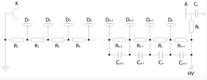
Fig. 2 Pulse signal potentiometer circuit
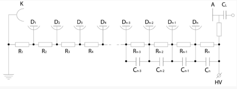
Fig. 3 Fast-time-responsive potentiometer circuit
In a high-voltage supply circuit, a low-pass band filter consisting of R1 and C1 is connected to reduce noise from high-voltage supply. Generally, the resistance is several 10 kΩ and the capacitor is 0.001~0.05μF high voltage-resistant ceramic dielectric capacitor.
When a high-speed pulse with a rise time of less than 10ns is output, as shown in Fig. 3, the oscillation of waveform can be reduced by connecting damping resistors R9 and R10 in the last stage dynode and the corresponding front stage dynode. The damping resistor is usually about 10~200Ω non-inductive resistance. If the damping resistance is too large, it will cause the change of time response characteristic. Generally, the necessary minimum limit value can be determined by observing the actual waveform. Fig. 4 shows the output waveforms observed with a usual potentiometer circuit and a potentiometer with damping resistors, respectively. It is obvious that the circuit oscillation with the damping resistors is much reduced.
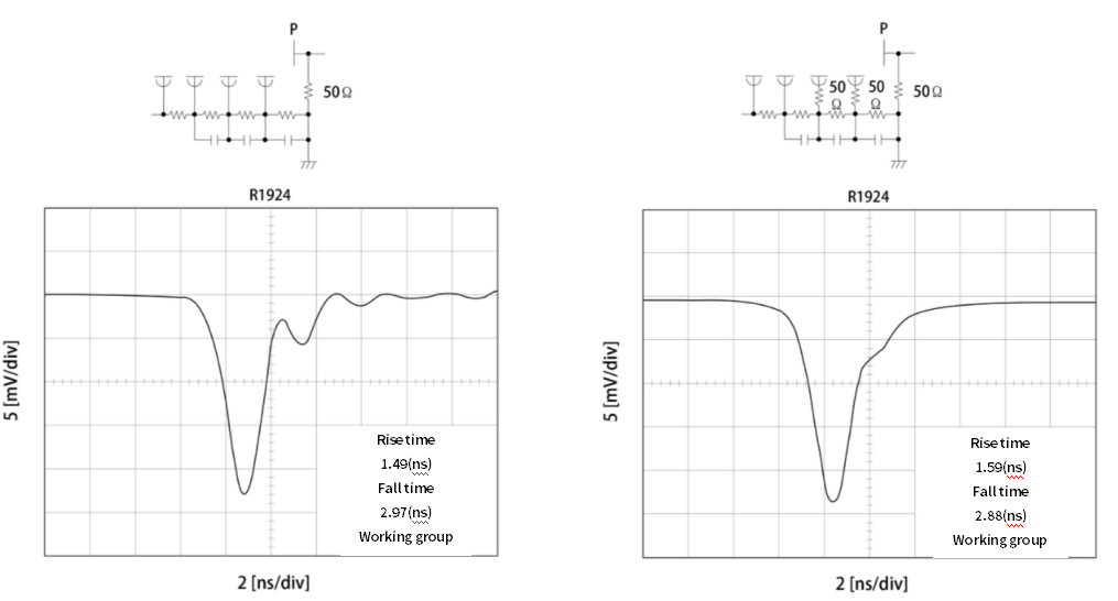
Fig. 4 Effect of damping resistor
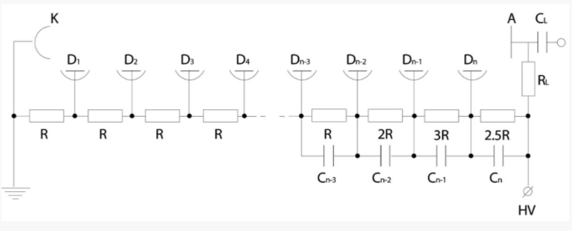
Fig. 5 High linear (high current) output potentiometer circuit
The voltage ratio of the potentiometer with optimal pulse linearity varies with the type of the PMT. In the application field of high energy physics, because of the often demand of high pulse output, there are recommended high pulse linear potentiometer voltage ratio (commonly known as cone potentiometer) and maximum output current value in the PMT sample. With this cone potentiometer (Fig. 5) and the pulse linearity results measured with the usual potentiometer, as shown in Fig. 6, it is apparent that the pulse linearity can be improved by about 10 times by using the cone potentiometer. In addition, the anode output of the cone potentiometer is about 1/5 lower than that of the usual potentiometer, so the operating voltage must be increased during use.
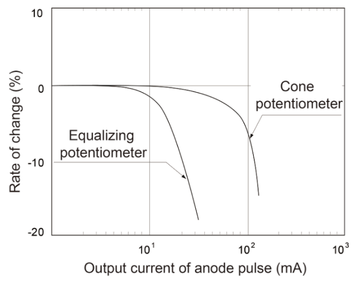
Fig. 6 Linearity with a cone potentiometer
Note: Pulse width: 50(ns): 50(ns);Vibration frequency: 1(kHz);1(kHz);Operating voltage: 1500 (V)1500(V)
PMT working environment
Light shielding
The PMT is a very sensitive photodetector, with weak detected signal. Therefore, special attention must be paid to the shielding of stray light. Where light leakage may occur, it must be sealed with black rubber. The inside of the dark box shall be coated with black light absorbing material to prevent light reflection and scattering.
Electric field shielding
The housing (for PMT) is usually made of aluminum metal or the like, which can effectively shield the external electric field if kept grounded. To prevent scattering and reflection of light, the interior of the housing needs to be blackened. In particular, good contact should be kept between the grounding wire and the connection. Also, if an object at ground potential is close to the housing of the PMT, this will increase the noise. Therefore, a certain distance must be maintained between the housing and the PMT.
Magnetic field shielding
The PMT is very sensitive to magnetic fields, and even the intensity of the earth magnetic field has an adverse effect on its properties. Therefore, it is necessary to use magnetic shielding cylinder or magnetic shielding dark box for precise light measurement and light measurement in a strong magnetic field. Permalloy is the best shielding material. For the head-on PMT, special attention shall be paid to shield the section from the photocathode to the first dynode, and the length of shielding shell shall be half to one PMT diameter exceeding the photocathode surface.
Noise reduction method
One of the main causes of noise is thermionic emission, which dominates in the general range of voltages used. If the environment used requires noise reduction, the temperature reduction approach is feasible. Fig. 7 is the dark pulse temperature characteristic curve of different photoelectric cathode.
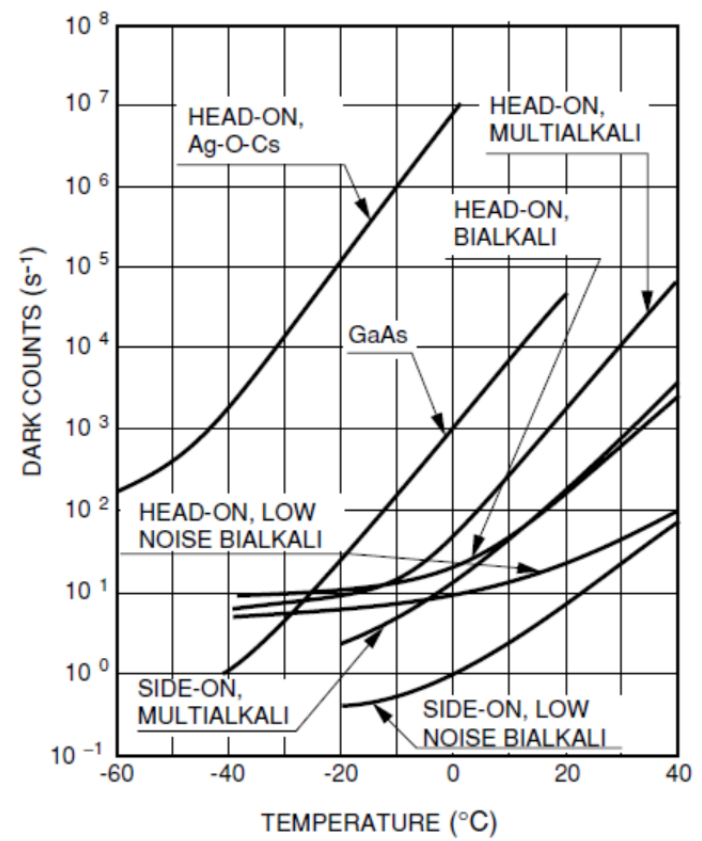
Fig. 7 Temperature characteristics of the dark-current pulses
Conclusion: The PMT is a very sensitive photodetector. In order to make better use of the PMT and achieve best performance, it is very important to design the matching operating voltage ratio. In addition, when using the PMT, we should pay attention to shielding to avoid environmental impact on the PMT performance.