


Supports
The linearity of the PTM refers to the linear relationship between the anode output current of the PTM and the incident light flux. The linear characteristic has important application in the field of faint light and scintillation detector. The scintillation detector composed of scintillator and PTM transforms radiation signal into pulse current signal to measure radiation, which is one of the common detection means in the current radiation measurement. The sensitivity and linear dynamic range of the scintillation detector are the main properties of the detector. The linear dynamic range of the scintillation detector is directly related to the pulse linear output performance of the PMT when the type and size of the scintillator are determined.
The linearity of the PMT is mainly related to the linearity of cathode and anode. The cathode linearity is determined by the cathode material, and the photoelectric surface is a semiconductor with certain resistance. For the photoelectric surface of the transmittance type, the linear current of the photoelectric surface is related to the type of photoelectric surface (see Table 1).
Table 1 Types and characteristics of photoelectric surfaces
Types of photocathode surfaces | Spectral response (Peak value) (nm) | Upper limit of linearity (average current) (μA) |
Ag-O-Cs | 300~1200(800) | 1 |
Sb-Cs | ~650(440) | 1 |
Sb-Rb-Cs | ~650(420) | 0.1 |
Sb-K-Cs | ~650(420) | 0.01 |
Sb-Na-K | ~650(375) | 10 |
Sb-Na-K-Cs | ~850(420)900(600) | 1 |
Ga-As(Cs) | ~930(300~700) | (※)0.1 |
Cs-Te | ~320(210) | 0.1 |
Cs-I | ~200(140) | 0.1 |
(※) Exceeding the labeled current value will shorten the service life
The anode output current may be affected by the linearity of the cathode when the PMT operates at low voltage and high current. Therefore, in order to reduce the influence of the photoelectric surface resistance, a power supply voltage of 100V to 400V is generally applied between the photoelectric surface and the first dynode.
The anode linearity is mainly influenced by the potentiometer circuit and the space charge effect of the multiplication system at high current. The influence of the potentiometer circuit on the linearity of the PMT can be divided into direct current mode and pulse mode by the working mode of the PMT.
When the PMT operates in the DC state (see Fig. 1), for the current flowing through the R7, the actual current flowing through the potentiometer is the difference between the potentiometer current Ib and the anode current Ip, and the other current flowing through the potentiometer is the difference between Ib and the dynode current IDy flowing through the potentiometer resistance from the opposite direction of each dynode.

Fig. 1 Direct current (DC) output potentiometer circuit
Because the anode current and the dynode current cancel with the potentiometer current, with the increase of incident luminous intensity, the voltage between the electrodes decreases. In particular, the decrease in the voltage between the back dynodes with very large current is more significant. The secondary electron collection efficiency of the anode is reduced, so as to produce saturation phenomenon, resulting in a linear decrease of the anode.
Although the linear current is different according to the type of the PMT and the potentiometer circuit, the actual maximum value of the output current shall be 1/20~1/50 of the potentiometer current when the DC output is obtained. If the linearity requirement is within ±1%, the maximum output must be controlled within 1/100.
When the PMT operates in pulse state, the maximum linearity output of the PMT, only using the resistor potentiometer circuit , is within a few tenths of the divider operating current.

Fig. 2 Pulse signal potentiometer circuit
A pulse signal type potentiometer circuit shown in Fig. 2 can improve pulse linearity. The last stages of the circuit are connected with a coupling capacitor to supplement the PMT charge to suppress the voltage drop of the end stage dynode and anode, thus greatly improving the pulse linearity. When the pulse width is very narrow and the duty cycle is small, this method is not limited by the potentiometer current. The linear current can reach the value when space charge saturation occurs at the dynode inside the PMT. Therefore, a peak output current thousands of times more than the potentiometer current can be obtained.
Even if the decoupling capacitor is used and sufficient pulse output linear countermeasure is adopted, when the interstage voltage is fixed, the saturation state will occur after reaching a certain value with increasing incident light flux. This is due to the space charge effect caused by the increase of electron current density, which hinders the normal transport of electron current. The amount of the saturation current varies in particular from the electrode structure of the dynode and anode near the end stage dynode of the PMT and the voltage applied between the electrodes. In general, we do not change the type of dynode, but increase the interstage voltage between the last stage dynode and the adjacent dynode to increase the electric field strength between the dynodes to improve the linear characteristic. The following measures are generally used to increase the linear current of the PMT.
① A higher voltage than the standard voltage distribution is used in the latter stages of high electron density, generally using a so-called “cone potentiometer” where the voltage rises gradually from the preceding stage to the subsequent stage. Fig. 3 shows the linearity of the output current of the PMT under different voltage division ratios.

Fig. 3. PMT linearity with different potentiometers
② The working voltage of the PMT can be increased to obtain a high electric field intensity between the electrodes and overcome the influence of space charge. Fig. 4 shows the relationship between the operating voltage and the anode peak current of the PMT.

Fig. 4 Relationship between PMT linearity and voltage
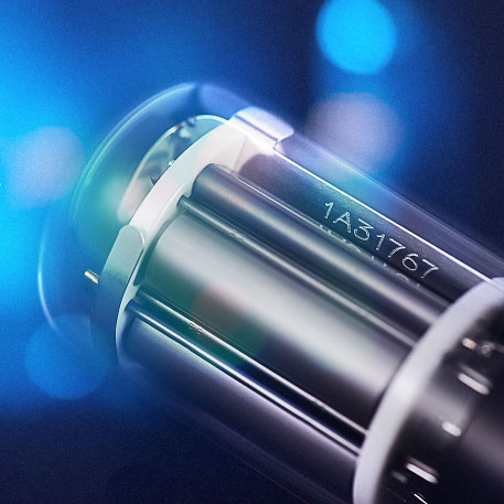
When there is a high demand for the pulse linearity of the PMT, the countermeasure of adding decoupling capacitor in the last several stages and using the voltage dividing circuit of the cone potentiometer can be adopted, and the appropriate working voltage can be loaded to make the PMT output larger anode peak current. CR332 (see Fig. 5) is characterized by small size, fast time response, good energy resolution and high SNR. Its typical linear current can reach 50mA@cone potentiometer at 5% linear deviation.

Fig. 5 CR332

Product: (86)-316-5970168/166/165
Other: (86)-10-63706370
E-mail: sctj@bhphoton.com