


Supports
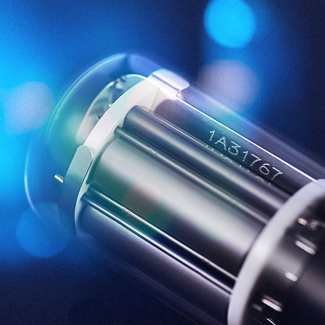
Photomultiplier Tube (PMT) may be mysterious to the users who first encounter it, but a thing or two can still be learnt from its name. “Photo” means the function, as the name implies, converts optical signals into electrical ones; “Multiplier” represents the structure of PMT, which is composed of multilevel multiplication poles used to amplify the electrical signals that are converted; “Tube” refers to the shape, the main body of typical PMT is cylindrical, but with the increase of application demand and the development of technology, shapes of PMT have become more and more various, as shown in Fig. 1.

Fig. 1 Various shapes of PMT
Typical PMT is a kind of vacuum glass tube, which consists of the faceplate, photocathode, electron multiplier, anode, and etc, as shown in Fig. 2. Incident light reaches the photocathode surface after passing through the faceplate, and photons are converted into electrons because of the photoelectric effect. Electrons are multiplied by a secondary emission process, which are then collected by the anode as an output signal. In addition, there are some photomultiplier tubes with special appearances and structures, such as Channel Photomultiplier (CPM) and Micro PMT (μPMT), which will not be specially introduced here. We will take the typical PMT as an example to introduce the characteristics of each part in the following.

Fig.2 Construction of a photomultiplier tube
1. Faceplate :
Different window material differs greatly in the absorption characteristics of UV-light, which also determines the short wavelength cutoff of spectral response, as shown in table 1.
Table 1 Window materials of PMT
Window materials | Short wavelength(nm) | Characteristic |
Borosilicate glass | 300 | It is the most commonly used window material. Because the borosilicate glass has a thermal expansion coefficient very close to that of the Kovar alloy which is used for the leads of PMT. |
UV glass | 185 | UV glass transmits ultraviolet radiation well |
Synthetic silica | 160 | The graded seal*1 is very fragile and proper care should be taken when handling the tube. In addition, helium gas may permeate through the silica bulb and cause an increase in noise. Avoid operating or storing such tubes in environments where helium is present. |
Sapphire | 150 | Sapphire shows an intermediate transmittance between the UV-transmitting glass and synthetic silica in the ultraviolet region. |
MgF2 crystal | 115 | Low deliquescence |
*1:Since the quartz glass has a big different thermal expansion coefficient from Kovar, which is used for the tube leads, borosilicate glass is used for the stem and a graded seal using glass with gradually different thermal expansion coefficient is connected to the quartz window.
2. Photocathode
Photocathodes are a kind of semiconductor materials. Valence electrons of the material absorb photon energy and spread to the surface when incident light occurs, turn into free photoelectrons after passing through the vacuum barrier and then launch into the vacuum. The occurrence of this phenomenon has a certain probability, which is defined as quantum efficiency (will be discussed in subsequent articles). Photocathode can be divided into reflection type and projection type according to the photoelectron emission process, and the corresponding window types are side-on type and head-on type.
Alkali metal materials and production process of photocathode determine the maximum response wavelength and long wave cutoff wavelength of PMT, the common types are shown in table 2, and determine the difference of color, as shown in Fig. 3.
Table 2-1 Characteristics of reflection mode photocathodes


Table 2-2 Characteristics of transmission mode photocathodes

3. Electron multiplier
Movement of PMT electrons is determined by the electric field, while electric field is subject to electrode shape, electrode configuration and voltage. In order to optimize the PMT, potential distribution and electrode structure need to be optimized. Photoelectrons emitted by the photocathode are multiplied by electron multiplier from the first dynode to the end (up to 19), and can obtain a current gain of 10 to 108 times.
Dynode has many kinds. Variation of PMT’s structure and multiplier number will lead to the difference in current gain, time response characteristics, uniformity and secondary electron collection efficiency. We should make corresponding choices according to the intended use. Multiplier types are shown in table 3.
Table 3 Typical characteristics for dynode types
Dynode Type | Features | Apply PMT type | Profile map |
Circular-cage | Compact, high speed | All side-on PMTs and in some head-on PMTs |
|
Box-and-grid | High collection efficiency | Head-on PMTs |
|
Linear-focused | High speed, high linearity | Head-on PMTs |
|
Venetian blind | Suited for large diameter | Head-on PMTs with a large photocathode diameter |
|
Mesh type | High magnetic immunity, high linearity | Head-on PMTs Used in high magnetic fields |
|
MCP | High speed | Used in high magnetic fields |
|
Metal channel | Compact, high speed | Stable gain even in magnetic fields |
|
Electron bombardment type | High electron resolution | - |
|
4. Anode
The anode of PMT is responsible for the collection of secondary electrons that are multiplied by the various levels, and the output of the current signal through the external circuit. The anode structure should be designed to ensure that the potential difference between the anode and the end dynode is suitable to avoid the space charge effect, thus obtaining a large output current.

Product: (86)-316-5970168/166/165
Other: (86)-10-63706370
E-mail: sctj@bhphoton.com